Performance Modeling
Pavement performance modeling is essential for good pavement management practice on all levels, from the project level to the network level. Pavement performance models are generally developed based on historical pavement data combined with engineering judgment.
Pavement performance models can be broadly divided into two categories: group models and pavement management section models. Group models are models developed for a group of sections based on a set of categorical criteria, such as Pavement Type, Traffic Level, Client Region, etc. On the other hand, Pavement management section models are models that are specified for each pavement management section based on its characteristic features. AgileAssets Pavement Analyst uses group-based models where a group is a set of pavement segments defined by one or more variables. These variables are called Performance Class Variables.
1.1 General Performance Model Setup
AgileAssets Pavement Analyst uses linear regression analyses, performed on actual historical condition information, in conjunction with other factors known to affect performance.
The system produces a wide range of deterministic models for groups of similar pavements. The software is highly flexible in terms of allowing these models to be developed and analyzed automatically as well as visually examined for their accuracy and reliability. User-defined models are also allowed to supplement cases where the data is inadequate to develop statistically valid models.
The general methodology for building performance models in the system is:
- Prepare a set of data composed of Y (condition index) and X (pavement age) from the performance master file.
- Transform Y (both the linear transformation, as applicable, and the 0 - 100 scale transformation).
- Divide the dataset into groups based on the Performance Class Variables.
- In each group, run regression analysis (linear or non-linear, as applicable to the model type) without removing any data points.
- Identify outliers.
- Remove all outliers from the data set and run the regression analysis again, if desired.
- Review the statistical outliers to determine if a user-defined set of outliers should replace the statistical outliers. Run the regression analysis again. Select the model or define user parameters until better data is available for the data set.
Several data elements must be configured before models can be specified:
- A set of Performance Index (PI) definitions must be developed.
- A set of Performance Model Types (i.e., Linear, Exponential, etc.) must be established.
- A set of Performance Class Variables must be defined.
Performance Class Variables define the homogeneous sets of pavement sections within the roadway network.
A performance class (model group) is defined for each combination of the values of the activated performance class variables. For example, if you have AADT and Functional Class as Performance Class Variables, and there are eight functional classes defined and three levels of traffic, then this produces a combination of 8 x 3 =24 groups for creating models and results in a matrix of groups as shown in the table below.
Low Traffic | Medium Traffic | High Traffic | |
Interstate Urban | 1 | 9 | 17 |
Interstate Rural | 2 | 10 | 18 |
NHS Urban | 3 | 11 | 19 |
NHS Rural | 4 | 12 | 20 |
Arterial Urban | 5 | 13 | 21 |
Arterial Rural | 6 | 14 | 22 |
Non-Arterial Urban | 7 | 15 | 23 |
Non-Arterial Rural | 8 | 16 | 24 |
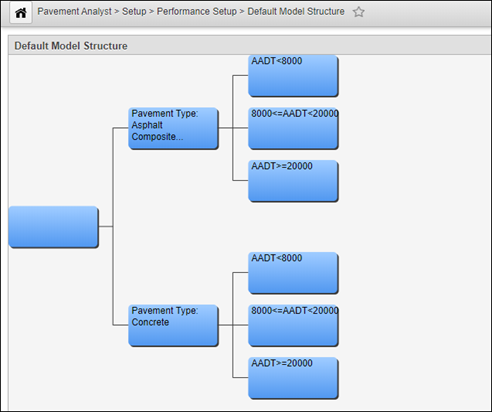
In the system this matrix is represented using a tree structure in the Default Model Structure window. Caution is recommended when choosing to use a Performance Class variable for modeling. When the number of performance classes is increased, the number of models that must be maintained increases exponentially. When selecting performance classes and defining their levels, keep in mind that depending on how you structure the model tree, the total number of models required by the system may be as many as the number of Performance Classes x the number of Defined Performance indices. Therefore, if you have 10 PIs and 24 Performance Groups you will need to create and maintain 240 models.
1.2 Default Model Structure - Click Here for General Performance Model Structure Exercises
The objective of this lesson is for the participant to understand how to Add a Node, Set Decision Parameters, and Delete a Node. At the end of this lesson, the user should know how to Add a branch to an existing node, Set Parameters for a parent node, and Delete a Node. |
|---|
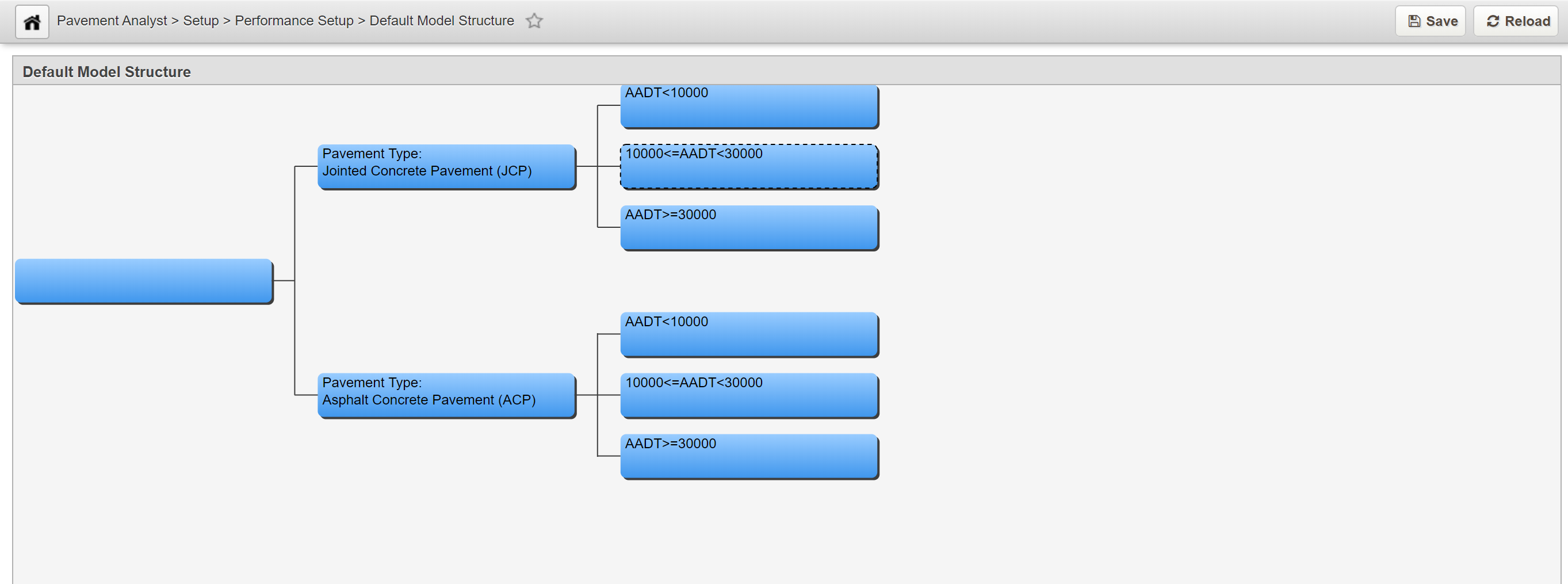
This window shows the decision process that determines what deterioration model to use for a particular type of section. "Type of road" means not only the type of road and how the road section is constructed, but also the condition attributes associated with that road section. Decision trees consist of parent nodes, child nodes, and the branches between them. The nodes are shown as boxes and the branches are the lines connecting the boxes. A parent node requires a user-selected decision variable and user-defined values to distinguish, and branch to, the parent's child nodes. The decision variables that may be used are selected in the Performance Class Variable column in the Setup PMS Analysis Columns window.
Each node of the tree represents the point at which a decision must be made. The tree then branches depending on the result of the decision. The user selects what decision variable is to be used in making the decision as well as the values for that variable that cause the different branches from the node to be selected. The tree is read from left to right, with the leftmost node representing the most general and the rightmost nodes the most specific. Out of the box, the system comes with a default model structure by Pavement Type and AADT level.
1.2.1 Add a Node
In this example, we add to an existing node by performing the following steps;
- Open the Default Model Structure window: Pavement Analyst > Setup > Performance Setup > Default Model Structure
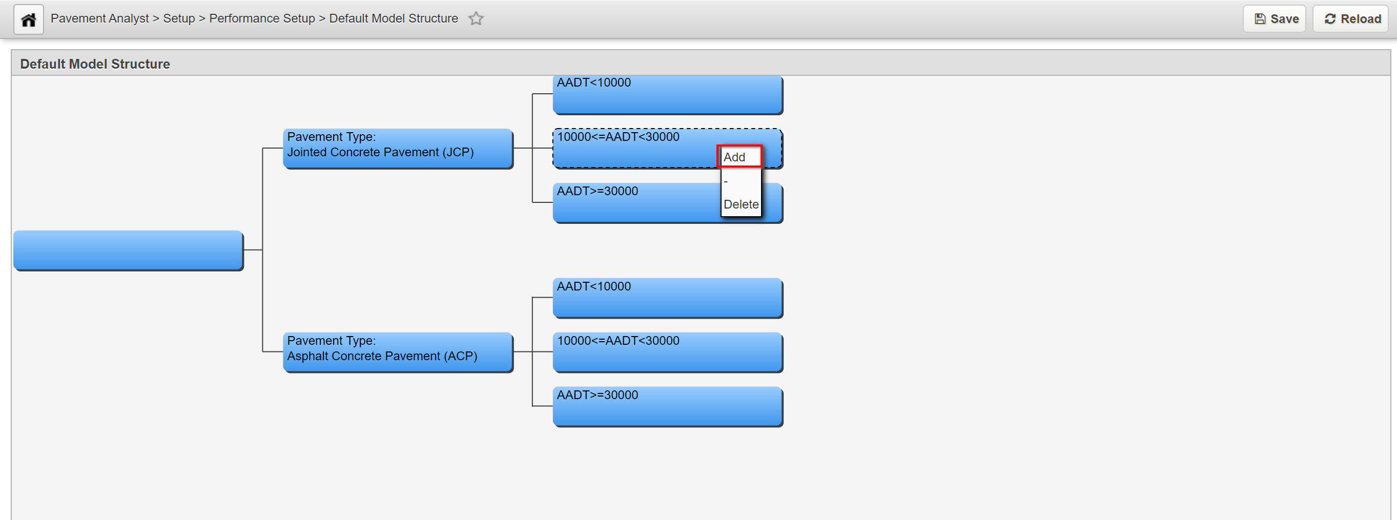
- Right-click the node to which the branch will be added and select Add.
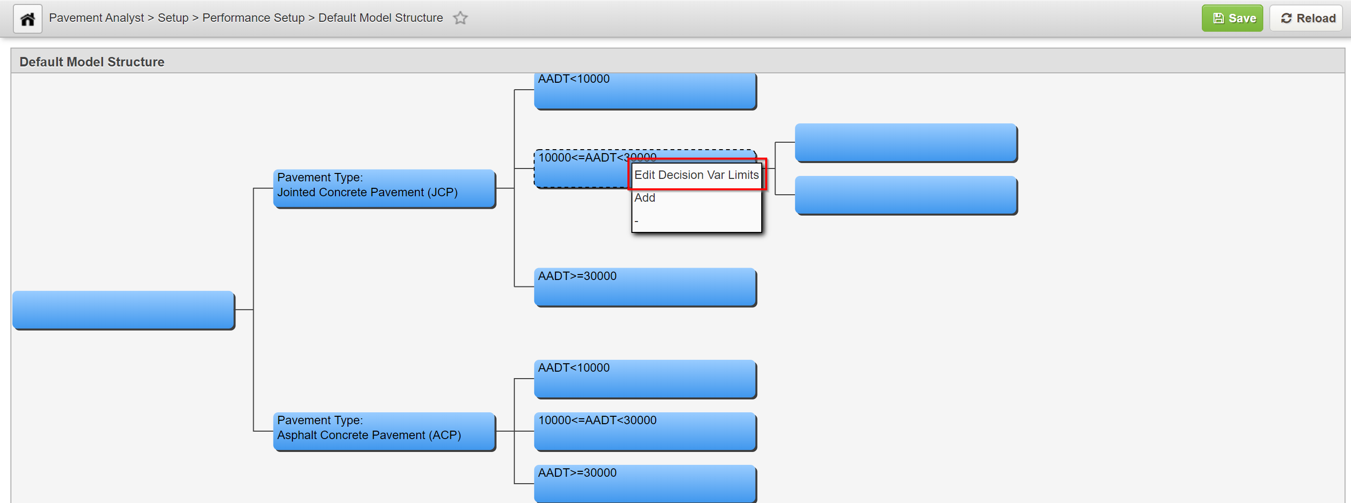
- If the node did not have any existing child nodes, the system creates two new child nodes. Each child node will be given the default description of No Model.
- If the node already had child nodes, then the system will create only one new child node. This child node will be given the default description of No Model.
1.2.2 Set Decision Parameters
Only parent nodes have parameters. These parameters determine which path through the decision tree is followed depending on the conditions encountered in the performance model.
In this example, we set the parameters for a parent node by performing the following steps:
.
- Right-click the parent node that will have its parameters set and select Edit Decision Var Limits.
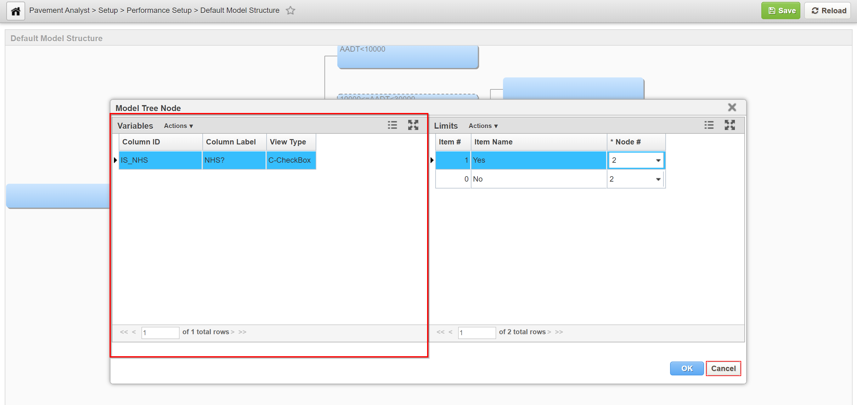
2. The system displays the dialog box for setting the node's parameters. The Variables pane on the left side of the dialog box shows the decision variables that can be used for this node. In any branch of the decision tree, a decision variable can only be used once. If no decision variables are shown in the left pane, this means all decision variables have been used in this branch. To add decision variables, navigate to the Setup PMS Analysis Columns window (Pavement Analyst > Planning > Setup > Network Analysis Setup > Setup PMS Analysis Columns) and check the desired variables in the Perf. Class Variable column.
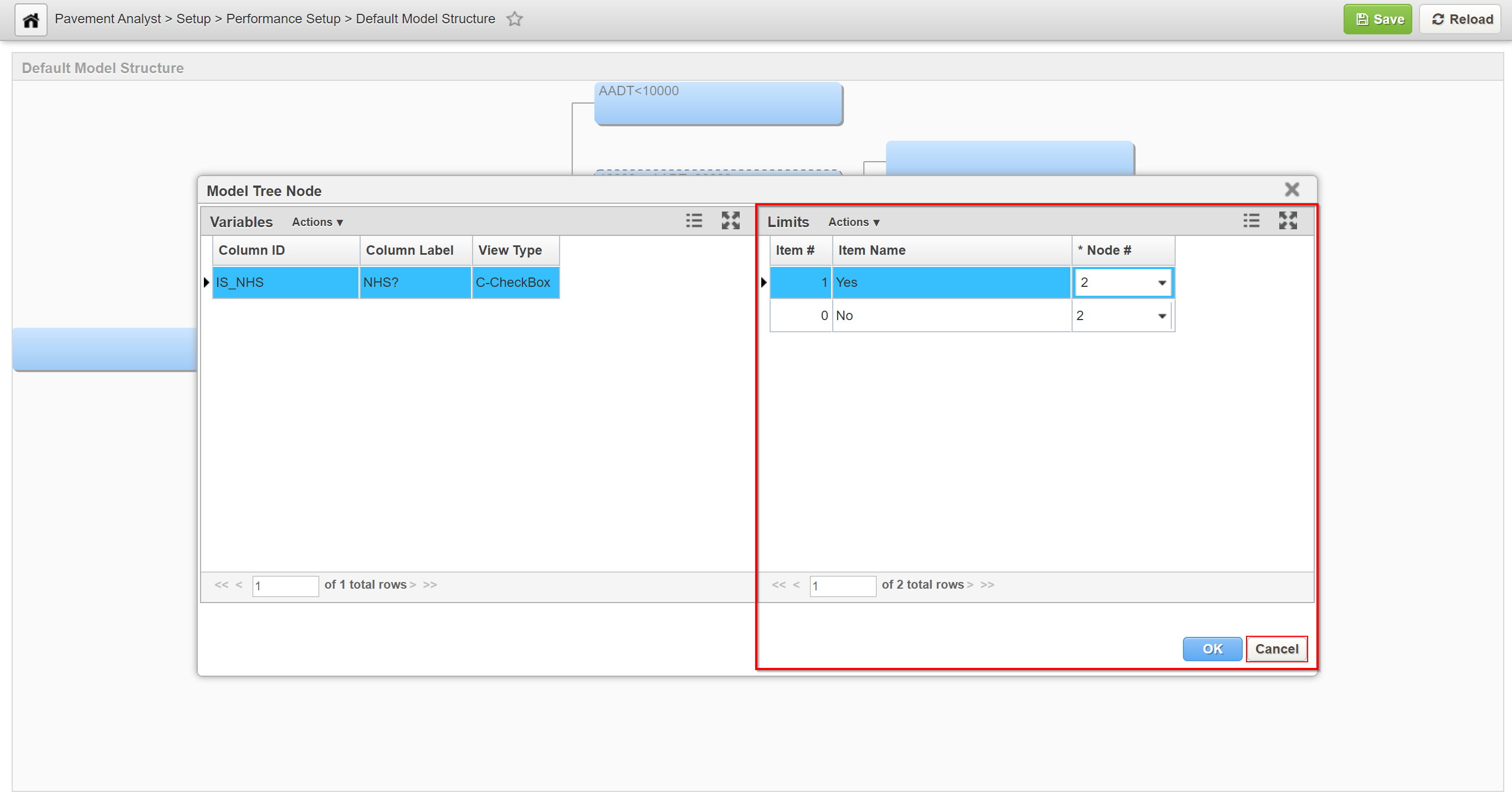
3. The Limits pane on the right side of the dialog box shows the value assigned to each child node for the variable selected in the left pane. (Child nodes are identified by a number, with node number 1 at the top of the window.) Variables can be configured to have either numeric or character values. If the variable is configured to have numeric values, then the right pane shows a record for each child node. Each record shows the upper threshold at which the next child node will be activated. The upper threshold of the first child node then becomes the lower threshold of the next child node, and the process repeats for any additional child nodes. If the variable is configured to have character values, then the right pane shows all character values that can be assigned to the variable. You assign a node to each character value, with that node being activated when the variable equals the assigned character value. Note that not all values need to be assigned; use Node 0 for any character values you do not wish to assign. In other words, with numeric values you assign threshold values to the child nodes, while with character values you assign child nodes to the values.
4. In the left pane of the dialog box, click the decision variable that you want to use.
5. If the selected variable is configured to have numeric values, in the first row of the right pane, click in the Node # column drop-down of the first row. Select the value for the threshold when the next child node will be activated. If necessary, repeat this action for any additional rows in the table (other than the last row, which is not assigned an upper threshold). Below is an example.
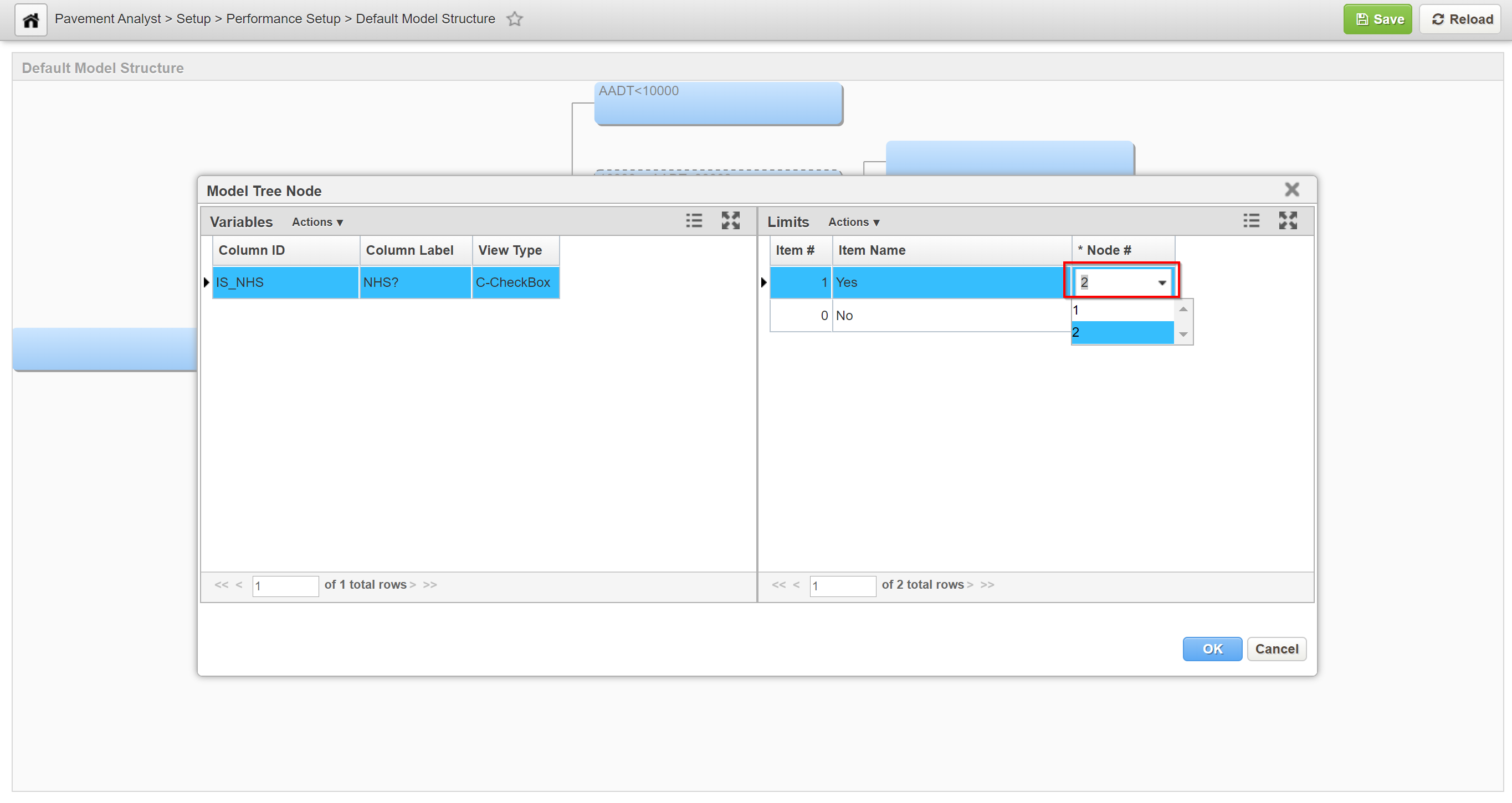
6. If the selected variable is configured to have character values, for the first character value listed in the right pane, click the down arrow to display the list of nodes and select the node to which this value will be assigned. (If the value is not to be assigned, select Node 0.) Repeat this action for each character value in the right pane.
7. When all values are assigned, click OK to close the dialog box and save the new values.
1.2.3 Delete a Node
Note:
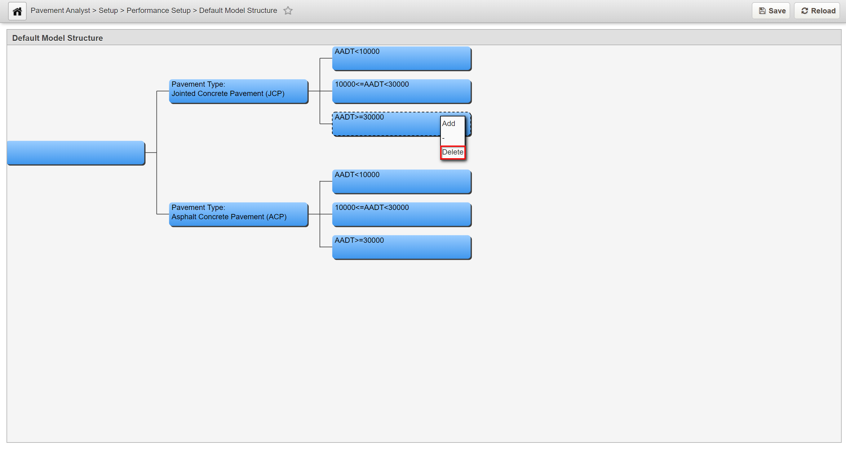
Only child nodes can be deleted. In addition, if the deletion of a child node leaves the parent node with only one child node, then the other child node will be deleted as well.
In this example, we delete a child node by performing the following steps:
- Right-click the node and select Delete. The system will then delete the node and branch.
2. Click the save button to save the changes.
