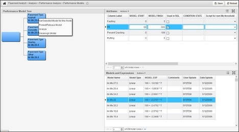
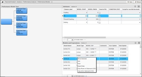
After Default Model Structure and Performance Model Expression have been configured, the Performance Models window (Pavement Analyst > Analysis > Performance Analysis > Performance Models menu) shows the assignment of which model expression is used for which group of performance class for any particular performance index (or condition attribute). The models configured in this window are then used in network analysis.
Use the Performance Models window to assign a model to a node of the decision tree for each condition attribute. Almost always, models are assigned only to the rightmost nodes. However, when all child nodes for a parent node would use the same model, you can assign a model to the parent node as a shortcut.
The Performance Models window has three panes: Performance Model Tree, (Condition) Attributes, and Models and Expressions.
For additional information, see the following topics:
Performance Model Tree Pane
For the condition attribute selected in the Attributes pane, the Decision Tree pane shows what models are assigned to the different nodes of the Performance Model Class tree (i.e., Default Model Structure). The box representing each node shows the assigned model: unless no model is assigned, in which case the decision variable used in selecting the node is displayed. (If you hover over a node, the system will display the decision variable and value that causes that node to be selected.)
When this pane is displayed, the system only displays a portion of the decision tree. You can view other parts of the decision tree by holding down the mouse key and then dragging the decision tree as desired. You can also change the magnification by using the wheel on the mouse.
Right-click Shortcut Menu Commands
When you right-click a node in the decision tree, the following special commands are available:
- Analyze Model: This command displays the Analyze Model window, which shows a time versus condition graph of the model assigned to the selected node. You can perform regression analysis from this window. (If no model is assigned to the node, the system uses the model currently selected in the Models pane.)
Disassign Model: When a node has a model assigned to it, this command disassociates the model from the node.
Note: If you want to replace an existing model, you can use the Set Selected Model for this Node command directly. The new selection will then replace the node's current model assignment with a different model assignment.- Protect/Release Model: Provided you have sufficient authority, you can "protect" the assignment of a model to a node. This means that the assignment cannot be changed until the protection is released (by you or someone with sufficient authority). Once a model assignment is protected, an asterisk (*) appears before the start of the model name. If you do not have sufficient authority, or if a model is not yet assigned to the node, this command is not available.
Set Model for Children: When all child nodes of a parent would use the same model for the selected condition attribute, you can right-click the child nodes' parent node and use this command as a shortcut to assign the model to each child node.
Note:The parent node must have a model already assigned to it before using this command. If no model is configured for the parent node, this command is not available.- Set Selected Model for this Node: For the condition attribute selected in the Attributes pane, this command assigns the model selected in the Models pane to the decision tree node that you right-clicked. If a model is already assigned to this node, the new selection replaces the previous selection. If a model is already assigned to this node, but is protected, the system displays an error message when you select this command because you cannot assign a model to a protected node.
Models and Expressions Pane
The Models and Expressions pane shows all available performance models. These are created and maintained in the Performance Models List window.
When you right-click a record (or group of records) in this pane, a shortcut menu is displayed with the following special command:
Show Selected Models: For the model(s) selected in the table, this command displays a new window that shows the selected models on a graph of time versus condition. (Select multiple rows by using either CTRL+click or SHIFT+click.)
Note: The permitted upper value along the Y axis is always 100. If the function of the curve is to exceed 100, then the system will display the curve as a flat line at 100 until the function of the curve returns to a value less than 100. Similarly, the X axis always displays 50 years: and if the curve reaches 0 before 50 years, the system will display the curve as a flat line along the X axis from the X-intercept to 50 years.
Attributes Pane
The Attributes pane shows all available condition attributes configured for your system. (A condition attribute is a measurement index such as rutting or cracking.) They are defined in the Deteriorates column of the PMS Columns in the Analysis window.
What you select in this pane determines what is displayed in the nodes of the Decision Tree pane. In other words, the models displayed in the decision tree are specific to a certain condition attribute. When you select a different attribute, the names of the models displayed in the nodes will also change.
Columns in the Attributes Pane
This pane provides the following columns:
- Column Label: This column shows the name of the performance attribute.
- Model Finish: This column shows the lower boundary value for the condition attribute. The default value is 0, but it can be set to a different value.
- Model Start: This column shows the upper boundary value for the condition attribute. The default value is 100, but it can be set to a different value.
- Benefit Threshold Groovy Script: This column provides a drop-down list that contains the various ways that the benefit threshold can be determined. This threshold is the lower boundary below which benefit is not calculated. This list contains all scripts configured in the Groovy Scripts window that are of the PI Threshold for RSL or Benefit type.
- Condition State: This column contains an expression that changes a raw performance index score into an integer value in the range of 1 to N, where N is the number of condition states. The integer value is then assigned a label in the Setup Condition State window to provide a word or phrase to describe the integer value: for example, 1 could be Very Good, 2 could be Good, and so on to 5 being Poor. These labels appear in the Detailed Scenario Analysis window as well as reports.
- Index Year Column: This is the name of the Network Master column that contains the year that the given index value is calculated from when filling the network master file.
- Script for Rem Life Threshold: This column provides a drop-down list that contains the various ways that the RSL threshold can be determined. This list contains all scripts configured in the Groovy Scripts window that are of the PI Threshold for RSL or Benefit type.
- Used for Ben. Calc.: When this check box is selected, the attribute is used to determine benefit.
- Used in RSL : When this check box is selected, the attribute is used to determine remaining service life (RSL).
Assign a Performance Model
Once the default model structure has been updated, the next step is to assign models to each of the right-most child nodes. This is accomplished in the Performance Models window as described below:
- In the Attribute pane, select the PI that the model is intended for
- In the Models pane, locate the model to be assigned to the first child node and then click the row showing this model to select it
- Right-click the first child node and then click Set Selected Model for This Node
The system displays the name of the model in the node - Repeat these steps for the remaining child nodes
- Click to save the new information


